RLC Damping
Solved the RLC circuit's differential equation for the damped current, then built the circuit and pulled damping coefficients off an oscilloscope to verify ζ = R/2L.
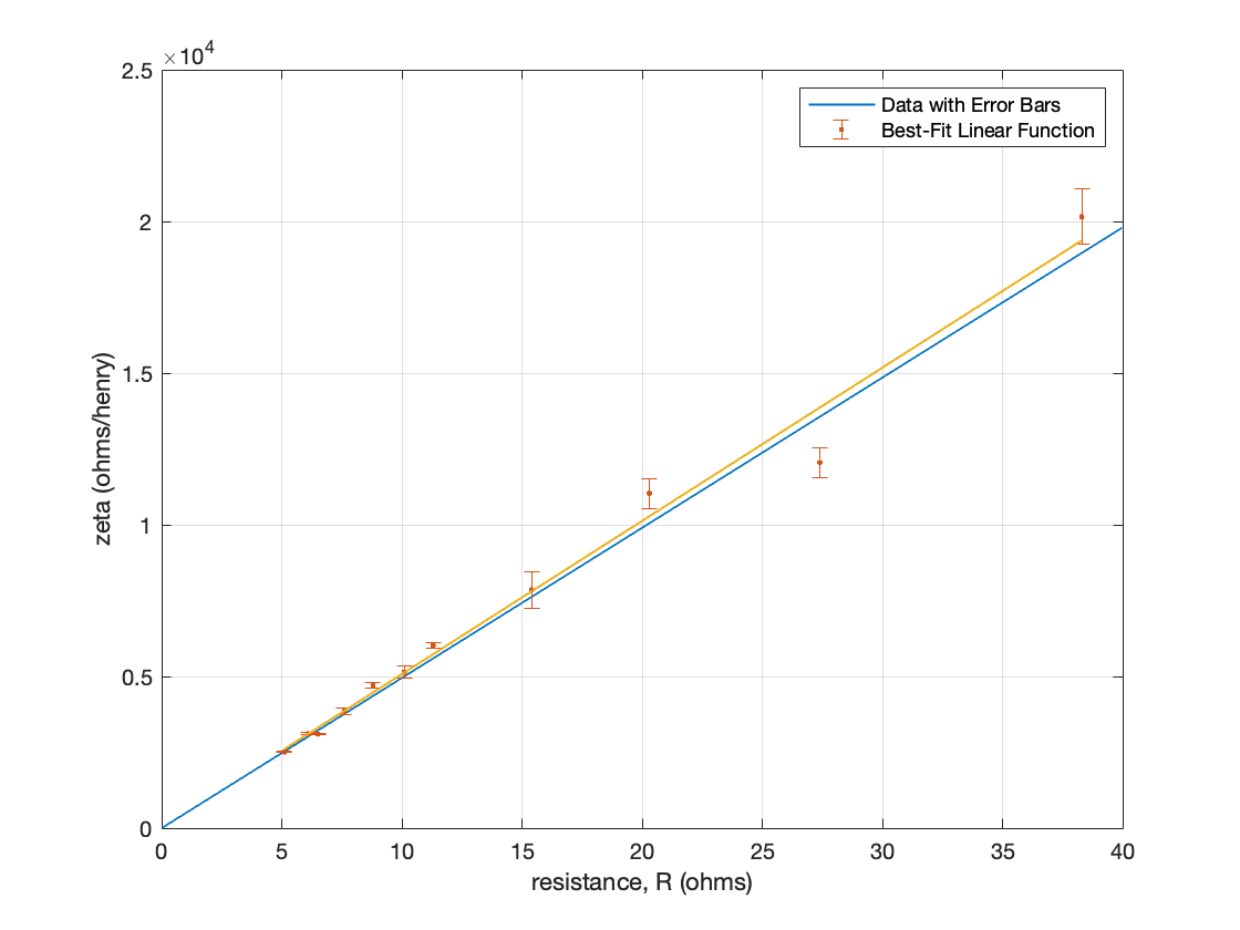
Testing LC oscillators in my radio builds, the carrier amplitude decayed instead of holding. Applying Kirchhoff’s voltage law to the RLC loop gives a second-order homogeneous ODE, and solving it yields a damped sinusoid whose decay envelope is governed by a damping coefficient ζ = R/2L. For the measured L and C, theory predicts ζ = (495 ± 5 H⁻¹) · R.
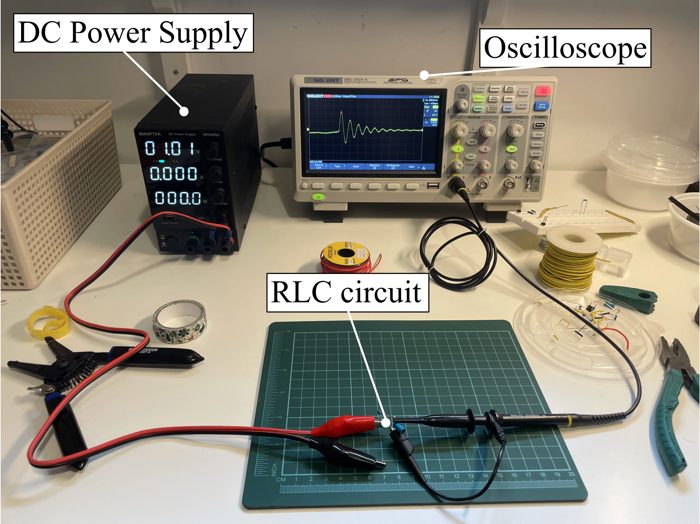
Ten series resistances up to the edge of critical damping, peak voltages read off the oscilloscope, and the natural log of the peaks plotted against time so each run’s ζ falls out as a line’s slope. Fitting ζ against total resistance gives a slope of 505 ± 22 H⁻¹ — a 2.04% deviation from theory.
The full derivation, raw peak tables, and uncertainty analysis are in the paper: