Monocular Hover
Training a small CNN to recover fingertip hover position from a single oblique low-res camera.
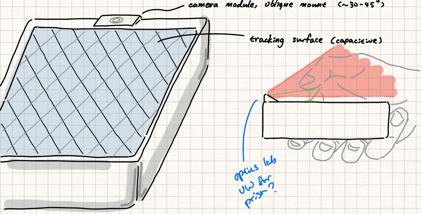
The offhand device is a VR peripheral touch surface that handles precise selection and UI. That surface has to track the fingertip hovering over it at 1 cm or better (in addition to touch sensing), to provide visual feedback to the user through VR goggles.
Problem
Capacitive hover itself is a difficult problem. The pad’s sensing stack must be tuned and shielded for touch to maximize resolution, and even at maximum sensitivity a close hover took ~3 s to register (due to weak coupling between the fingertip and sensor array). An alternative is optical sensing. Hand-tracking literature is egocentric, not device-centric with the finger foreshortened and self-occluding.
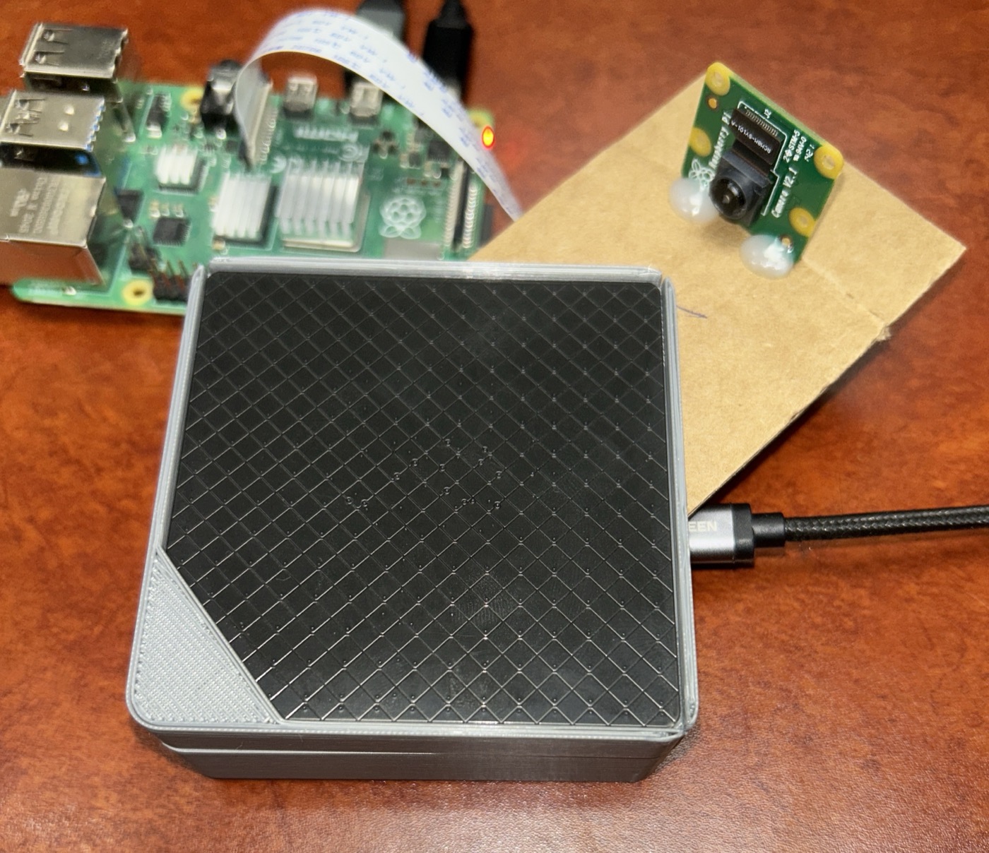
The goal was a kB-scale TinyML model on an MCU with a low-res (~100×100) camera. Validation stand-in was a Raspberry Pi 4 and Camera Module V2.1, with the model compressed and profiled for size, latency, and power.
Picking an inference scheme
Three candidate formulations:
- End-to-end — CNN maps the raw frame directly to normalized surface coordinates .
- Ray-plane — CNN finds the fingertip pixel ; calibrated intrinsics + extrinsics cast a ray and intersect it with the surface plane.
- LUT — CNN finds ; a per-session calibration lookup table maps it to .
Ray-plane is physics-based and survives lighting changes, but is sensitive to calibration-drift. The LUT absorbs lens and perspective distortion for free, but is session-specific. Both share irreducible depth ambiguity.
End-to-end has the simplest runtime and the whole hand is in frame, so the network can lean on context the tip-only schemes throw away.
The rig
- Camera:
raspicam_nodepublishing compressed frames over ROS, with a custom roslaunch file to run at 192×96 to profile to a 32-bit MCU training resolution. - Ground truth: a Trill Square capacitive sensor, read by an Arduino over I2C and streamed as
x ytouch events.
Labels without a mocap system
The capacitive pad reports touches, but the model must learn hover. There is no sensor in the loop that measures hover position directly.
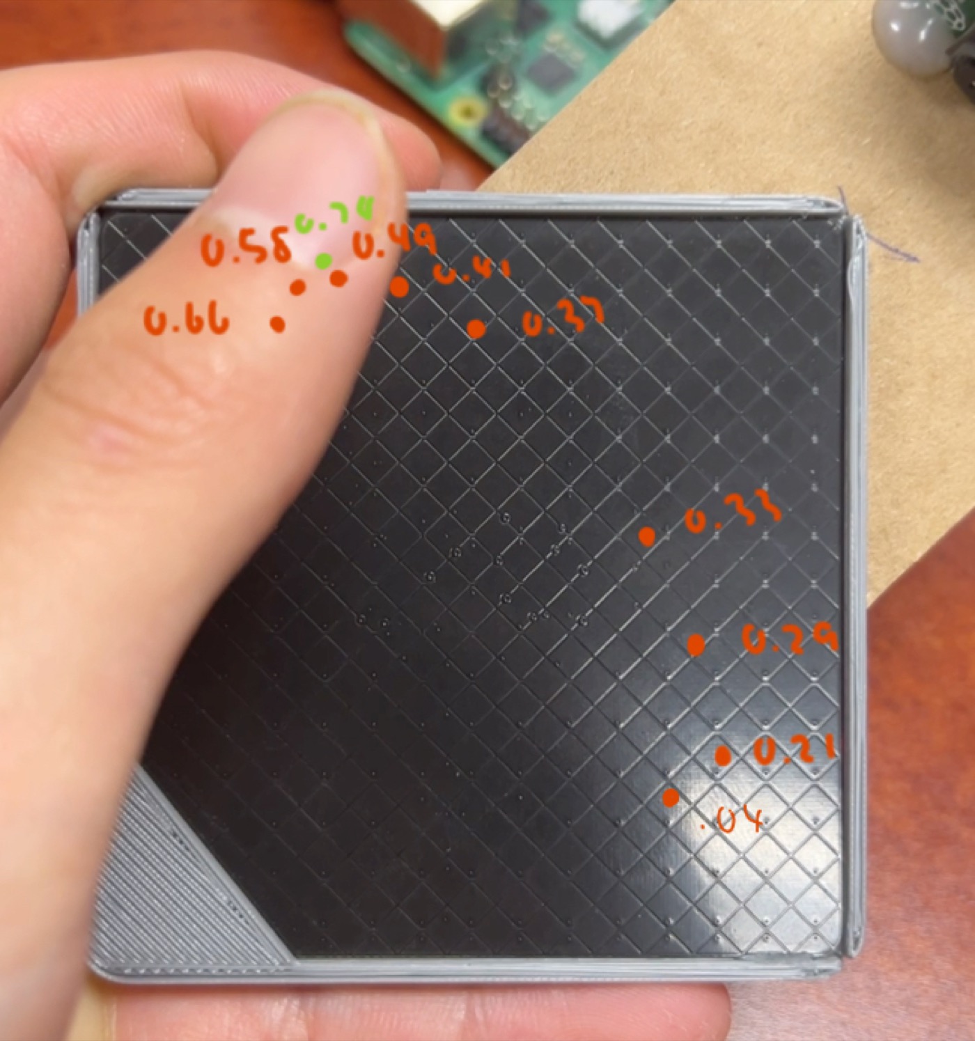
The workaround is interpolation. Two consecutive taps define a motion segment (touch down at , , touch up at , ). Every camera frame timestamped inside the segment gets a label interpolated between the endpoints, so sweeping a finger from tap to tap labels dozens of hover frames with two ground-truth contacts.
flowchart LR
    subgraph sensor["Sensor"]
        direction TD
        TS[Trill Square] -- I2C --> AR[Arduino]
    end

    subgraph ser["Serial reader (thread)"]
        direction TD
        RD[read serial lines] --> PS[parse touch state] --> QE[queue touch events]
    end

    subgraph lab["Labeler"]
        direction TD
        RQ[read off queue] --> CB[ROS callback] --> LF[label frames]
    end

    subgraph wr["CSV / frame write"]
        direction TD
        WI[write images] --> LG["log timestamp + (x, y)"]
    end

    sensor -- "(flag, x, y)" --> ser
    ser --> lab
    lab --> wr
Interpolating finger position between the endpoints requires assuming a speed profile. I cross-referenced candidate profiles (linear, cosine, logistic sigmoid) against top-view video of the same sweeps; sigmoid tracked the real motion best, which matches intuition: a finger accelerates out of the first tap and decelerates into the second.
The capture script seemed simple on paper but was rewritten several times to maintain accuracy and capture frequency against a starved main loop:
- Serial reads blocked the ROS callback and dropped touch events → moved to a dedicated thread feeding a queue.
- The GUI preview froze the program at high frame rates →
--headlessflag. - Sequential JPEG compression missed frames at 60 fps → ring buffer, batched processing, rate-limited polling.
- Writing to the SMB mount cost ~50 ms per frame → write to the local SD card, sync to the Mac after the session.
- Even the sigmoid computation got evicted: record raw timestamps during capture, interpolate in a separate pass.
Model
A MobileNetV2 backbone (last 30 layers fine-tuned) with a GAP → Dense(256) → Dropout → Dense(2, sigmoid) head regressing normalized under MSE, with brightness/contrast/flip augmentation.
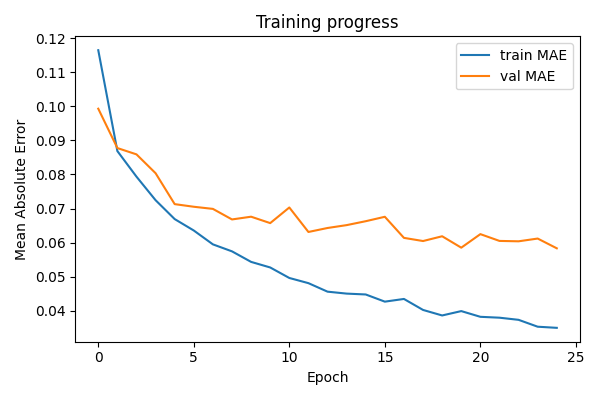
Validation MAE lands around 0.06 in normalized coordinates, about 4 mm on the 7 cm pad, from a 128×64 crop of a 192×96 stream. For a UI where the surface maps to a handful of hover targets, that is comfortably inside the budget.
The trained model converts to TFLite and runs on the Pi against the real camera stream, drawing the predicted position as a dot on a top-view canvas next to the camera feed.
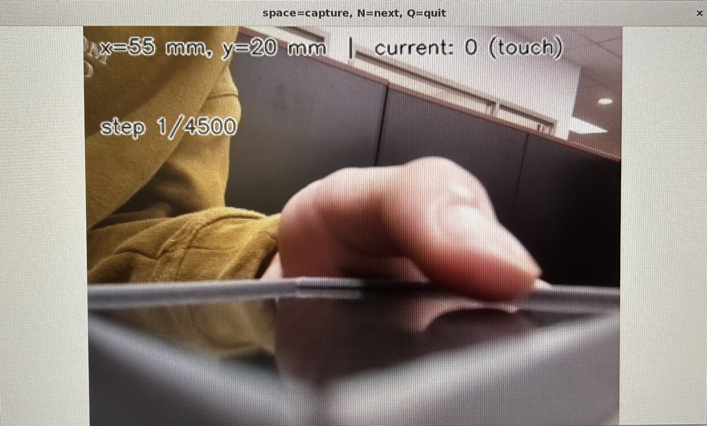
The concept validates: hover position is recoverable from a single device-centric oblique view, end to end, with no calibration step.
Python · TensorFlow / Keras · MobileNetV2 · TFLite · OpenCV · ROS · raspicam_node · Raspberry Pi 4 · Pi Camera V2.1 · Trill Square · Arduino · NumPy